Timing Pulleys
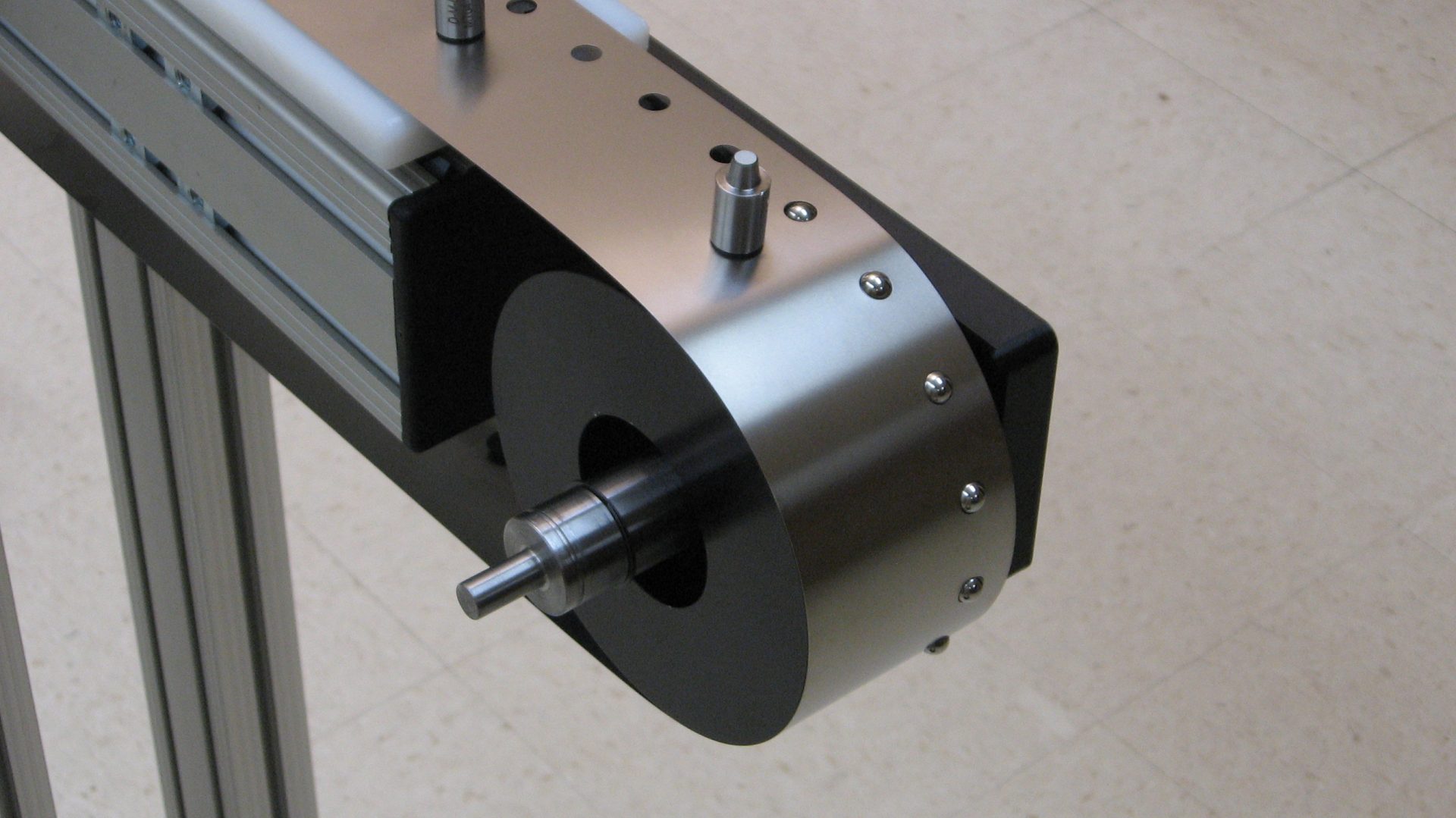
Timing pulleys have teeth or pockets around the outside diameter of the pulley body. Timing teeth engage holes in the metal belt, while timing pockets engage drive lugs on a belt’s inner circumference. As the name implies, these teeth or pockets are used for timing. The power transmission, or driving motion of the belt, is still accomplished via frictional forces between the flat belt and pulley surfaces.
Precise, Durable Results with Our Patented Ball Bearing Timing Teeth
Type I and II timing pulleys allow cycle repeatability without any pitch accumulation, also known as belt creep, within very precise tolerances. Repeatability is the ability of a single pitch on successive rotations of a belt to return to a home position within a specified tolerance—typically in the range of 0.002” (0.051 mm) to 0.005” (0.127 mm). In a friction drive system, the pulley moves slightly slower than the belt. If not controlled, belt creep in a friction drive metal belt results in a loss of repeatability, affecting the precision of the application. Using Type I or Type II timing pulleys is the best way to maintain system accuracy.
Timing elements—particularly timing teeth—must be highly resilient. The material’s hardness and durability is essential to ensure minimal wear from successive engagements of the belt and pulley. Belt Technologies’ patented timing pulley uses hardened ball bearings as teeth, which are specifically designed to provide added resistance to continuous wear and tear.
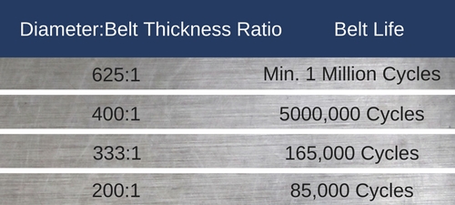
Achieve Maximum Belt Lifespan with Accurate Diameter Ratios
There are several important factors to consider when designing a pulley for a metal belt application, but the most important is the pulley diameter. The proper pulley diameter is a ratio of pulley diameter to belt thickness. As the diameter-to-thickness ratio decreases, belt bending stress increases and belt life is reduced.
When designing timing pulleys, it is important to ensure all timing elements have spherical or involute/evolvent radii. These radii guarantee smooth engagement and disengagement of the belt and pulley. To avoid problems resulting from accumulated tolerances, the diameter difference between driving and driven components should be at least ±0.005” (0.127 mm) to ±0.007” (0.178 mm). Zero or near-zero backlash applications are special cases.
When manufacturing a toothed pulley, each timing tooth is inserted into a hole that has been machined in the pulley body. Great care must be given to the radial location of each tooth to ensure overall pitch accuracy. It is also imperative for timing pulleys to have a pitch diameter at the neutral axis of the belt (one half the belt thickness for a thin flat belt), as opposed to the base. Metal belts are typically thin, a factor that is often neglected in calculating the pulley tape support diameter. Failure to include the belt thickness in these calculations almost always results in the mismatching of timing elements.
The tape support diameter can be determined by the formula:
D=NP/pi – t
Where:
N = Number of pitch lengths or teeth on a pulley
P = Perforation pitch
t = Belt thickness
High-Quality Timing Pulleys for Your System Designed by the Experts
The experts at Belt Technologies have the knowledge and experience to design and produce PureSteel®timing pulleys for your system that will provide highly accurate, repeatable product results. Our patented ball bearing timing teeth and in-depth understanding of the design requirements for timing pulleys will ensure that your automated system will last for the maximum number of cycles possible. Contact us today.